Geometry maps
The GPR method was initially developed to detect features and interfaces in the ground. We use the same technique to provide detailed geometry maps of concrete structures.
With the high accuracy of our GPR equipment, we can provide the thicknesses of the various layers composing the surfacing of a bridge deck. Furthermore, in a combination with calibration using core samples, we reach an accuracy of +/- 1 cm.
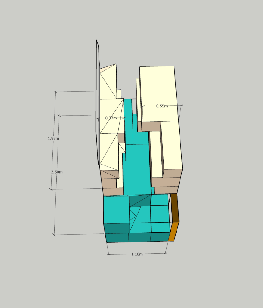
We can also provide detailed geometry of discrete elements or features such as rebar location and masonry blocks, with 3D models representing the accurate position and types of masonry stones.
Concrete cover map
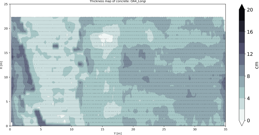
This map reveals the thickness of the cover concrete of the top layer rebars. It indicates the areas with a lack of concrete cover or potential over-thicknesses.
The removal depth and volume of material can be precisely estimated before an eventual hydrodemolition of the cover concrete.
Rebar spacing map
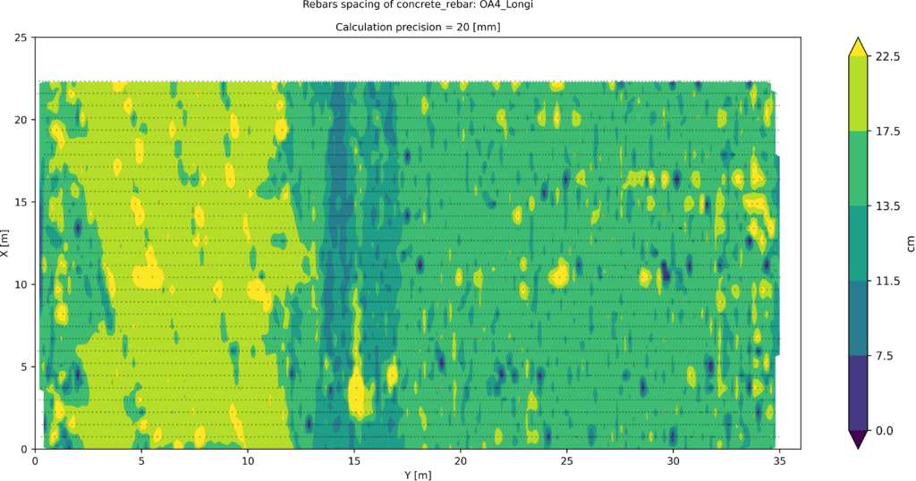
When the original blueprints are missing or incomplete, we can provide this map as a visual confirmation tool to determine rebar spacing in existing structures. The same principle is also applied to new structures.
The example on the right shows a concrete deck slab, where three distinct areas are revealed: the expected 150mm spacing on the right span, a higher rebar density around 15m on the supports, and a 4mm “anti-cracking” mesh on the left span with a 200mm spacing.
Asphalt Thickness Map
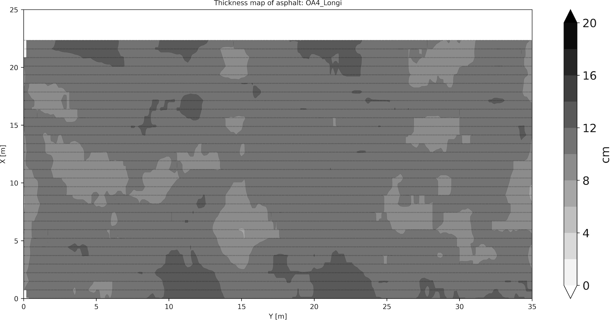
With this map, we can visualize the total thickness of the asphalt. Depending on its composition, we are also able to provide the thicknesses of its different layers. Similar to the concrete cover map, this map is a valuable tool to detect potential under-thicknesses or over-thicknesses.
Masonry geometry
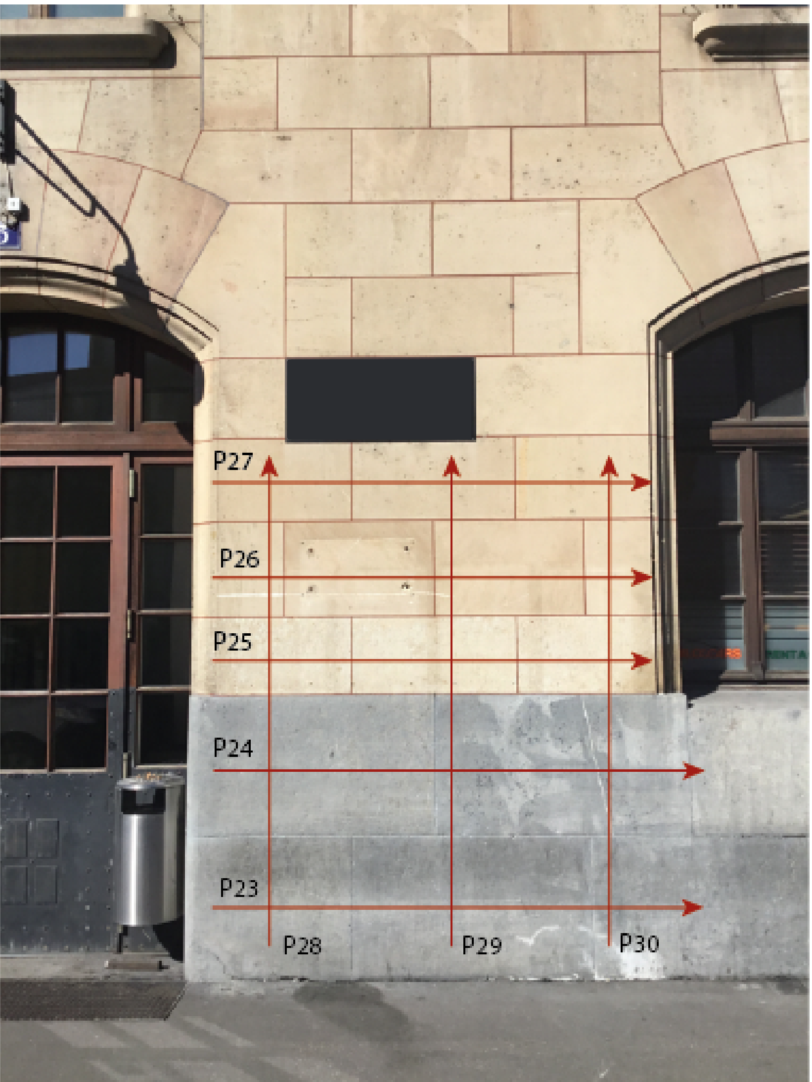
We have vast experience in analysing masonry structures, ranging from retaining walls over historical bridges to ancient roman theatres.
We can provide detailed 3D models with the thickness of cladding stones, the volume of infill and the location of steel reinforcement or anchor bars embedded in the walls.
BRIDGOLOGY
Le Grand-Chemin 73
Epalinges, CH-1066
T +41 79 297 40 54
info@bridgology.com
©Bridgology 2025
Designed by Swiss Backstage

